The "Literal" Mood Lamp
1. Research
These are some ideas I wanted to work on/got inspired by. I use the site Instructables. to find inspiration. Many people who have done a variety of projects upload their works there. I'm interested in making a light that has a sensor, such that when you place your hand on it, it lights up.
I also settled on the tutorial I wanted to follow for my lamp.
Right here
This is a silhoutte lamp. Depending on the way you choose to cut an image, a shape will be projected on the box when the light is turned on. I intend to make a silhoutte lamp that turns on when you place your hand on it.
These are some things I need
3ply plywood
switch
Ardino UNO board
HCS204 Ultrasonic Distance Sensor
Neopixel RGB light strip
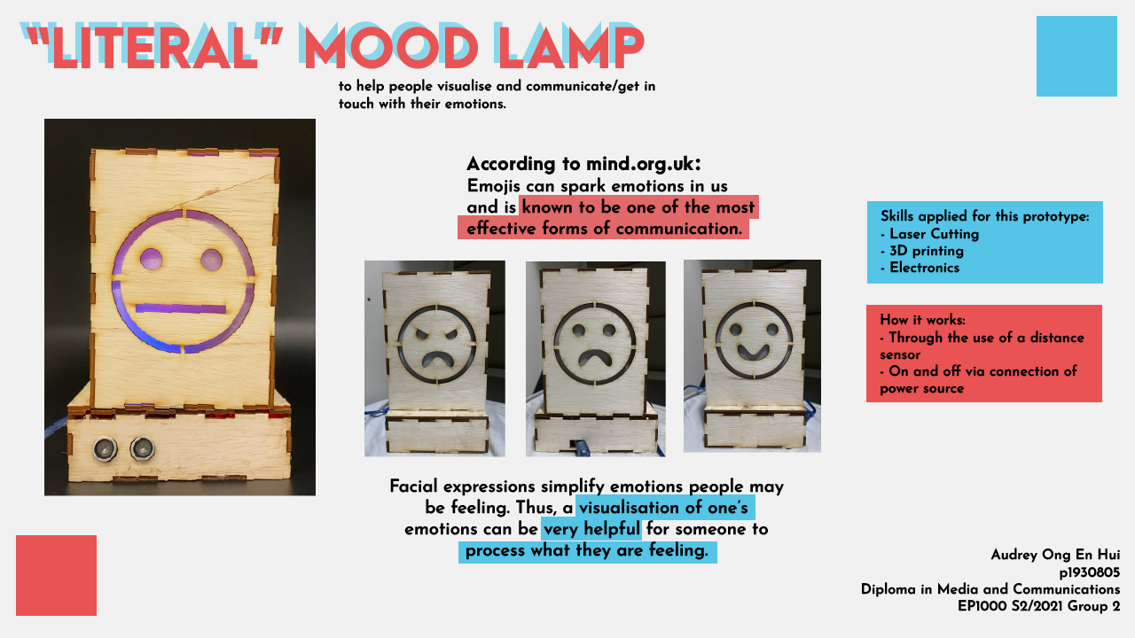
Concept: A literal mood lamp
My final project is like a "literal" mood lamp. Each side has different expressions. As per research, when we use emojis, a certain part of our brain lights up. Our minds are able to digest emotions better. In a sense, it helps for people to see and recognise facial features to resonate with how they are really feeling and process their emotional wellbeing. Mental health is something I am very passionate in. Knowing that is an important factor of "moods", I wanted to incoorperate that into the project. Hence, my project is a "literal" mood lamp, in which your personal mood is literally projected on a lamp and displayed before you. side note: My original idea was to have different sides a different colour, but sadly that was a bit too difficult to execute. Hence, I settled with changing colours.Implementation
Sketches
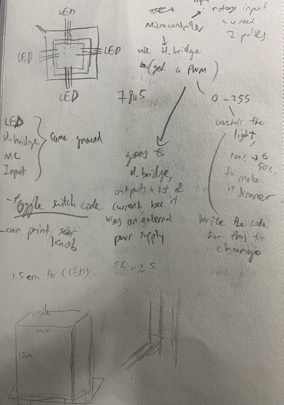
Here is me trying to plan out and take notes on the electronics of the project. At first I was going to do 3 different layers, I later found out this was too complicated and not feasible. But here I was operating on that basis.
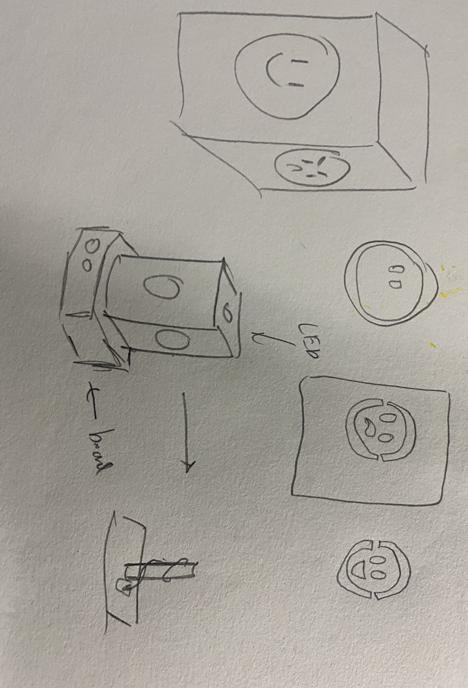
Here are my rough sketches of the project after cutting it down. I sectioned it as to how I would draw the faces and where I would put the UNO board and LED.
CAD
Next was designing it.
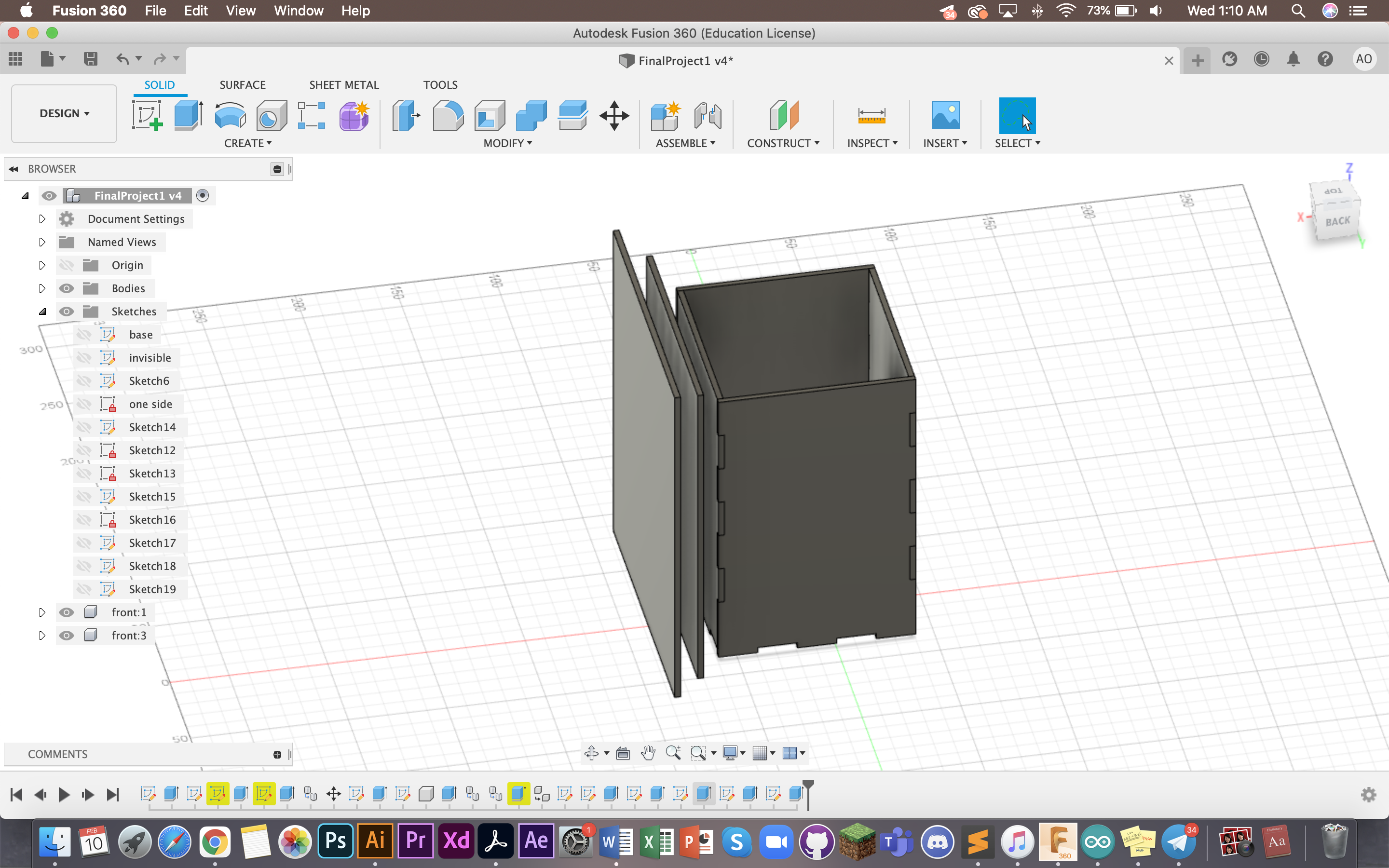
This is the original 3 layered box I was going to do. The first inner box to hold the UNO board, second with the design and third for the design to be projected. However, I discovered that if I were to do the 3rd layer, the design would not show up as it would be fully opaque (not the same material as what was used in the project I was adapting from)
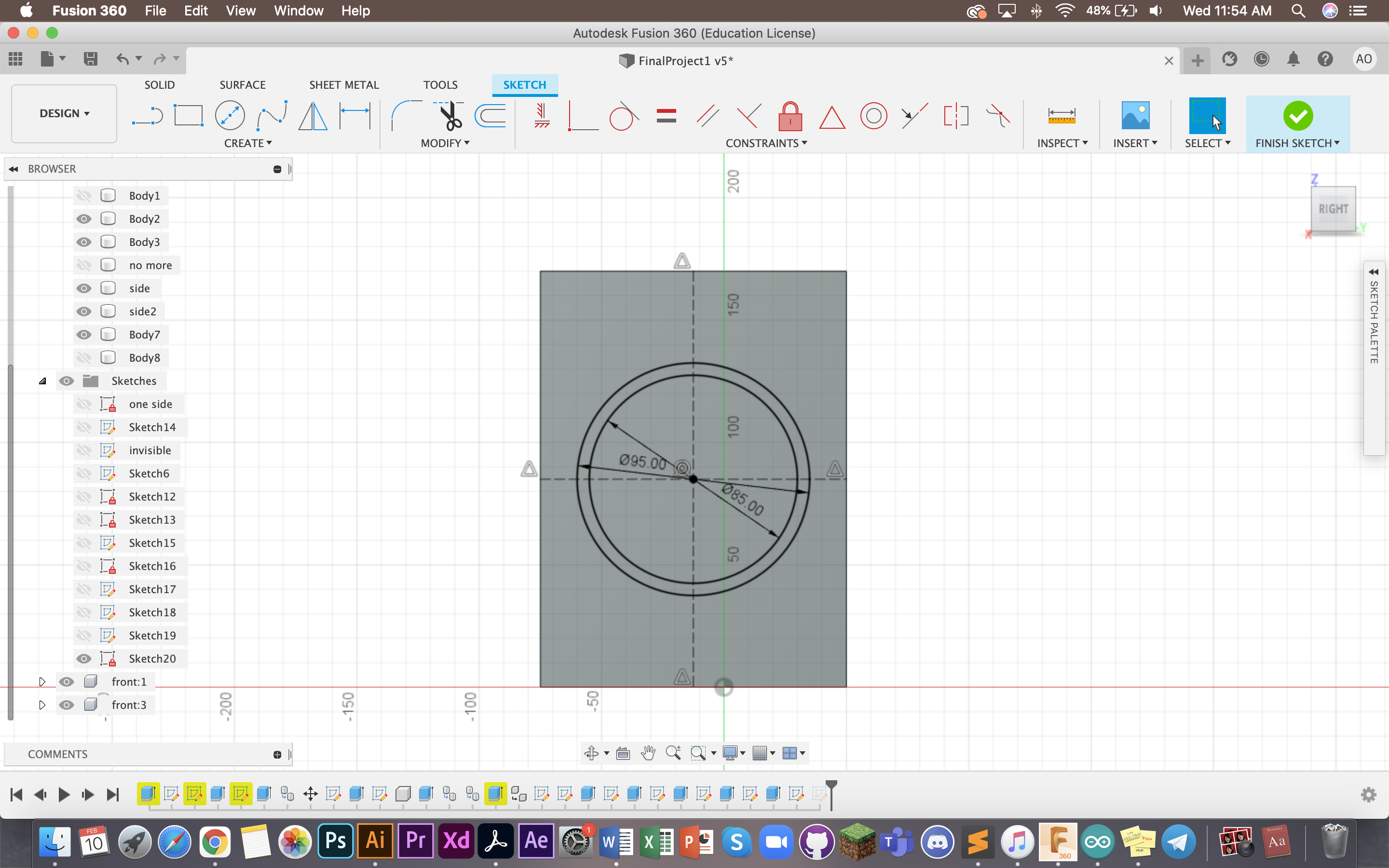
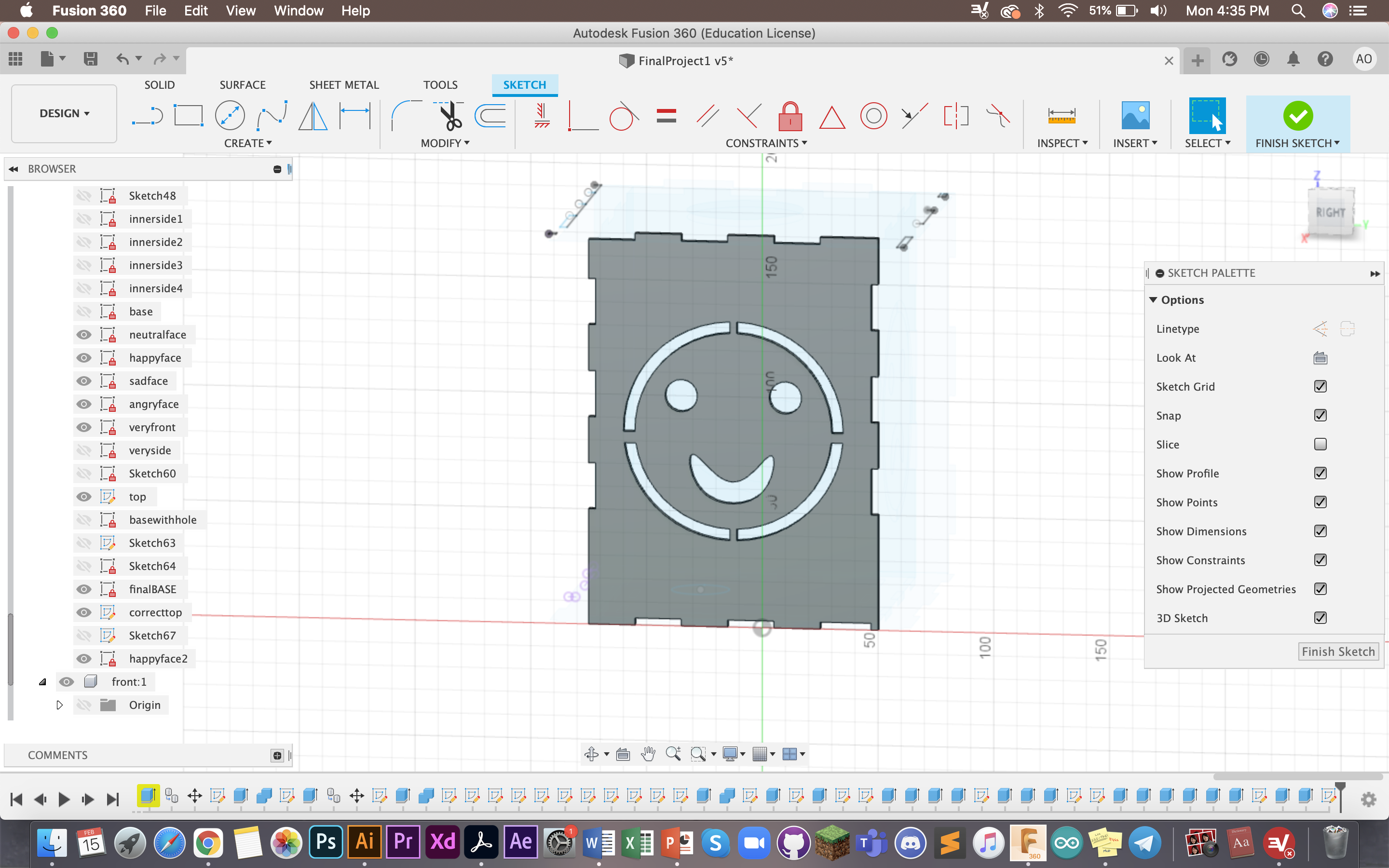
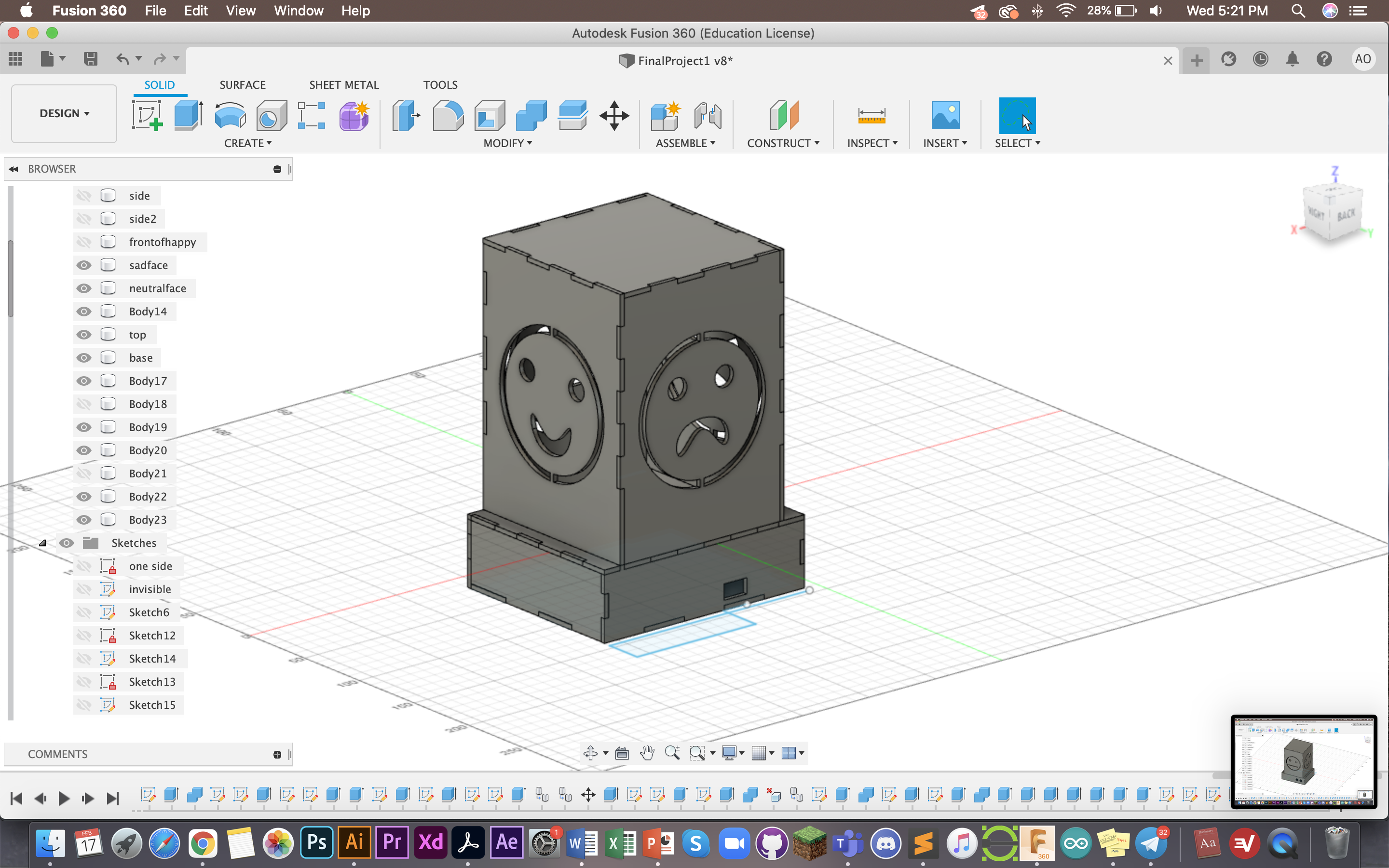
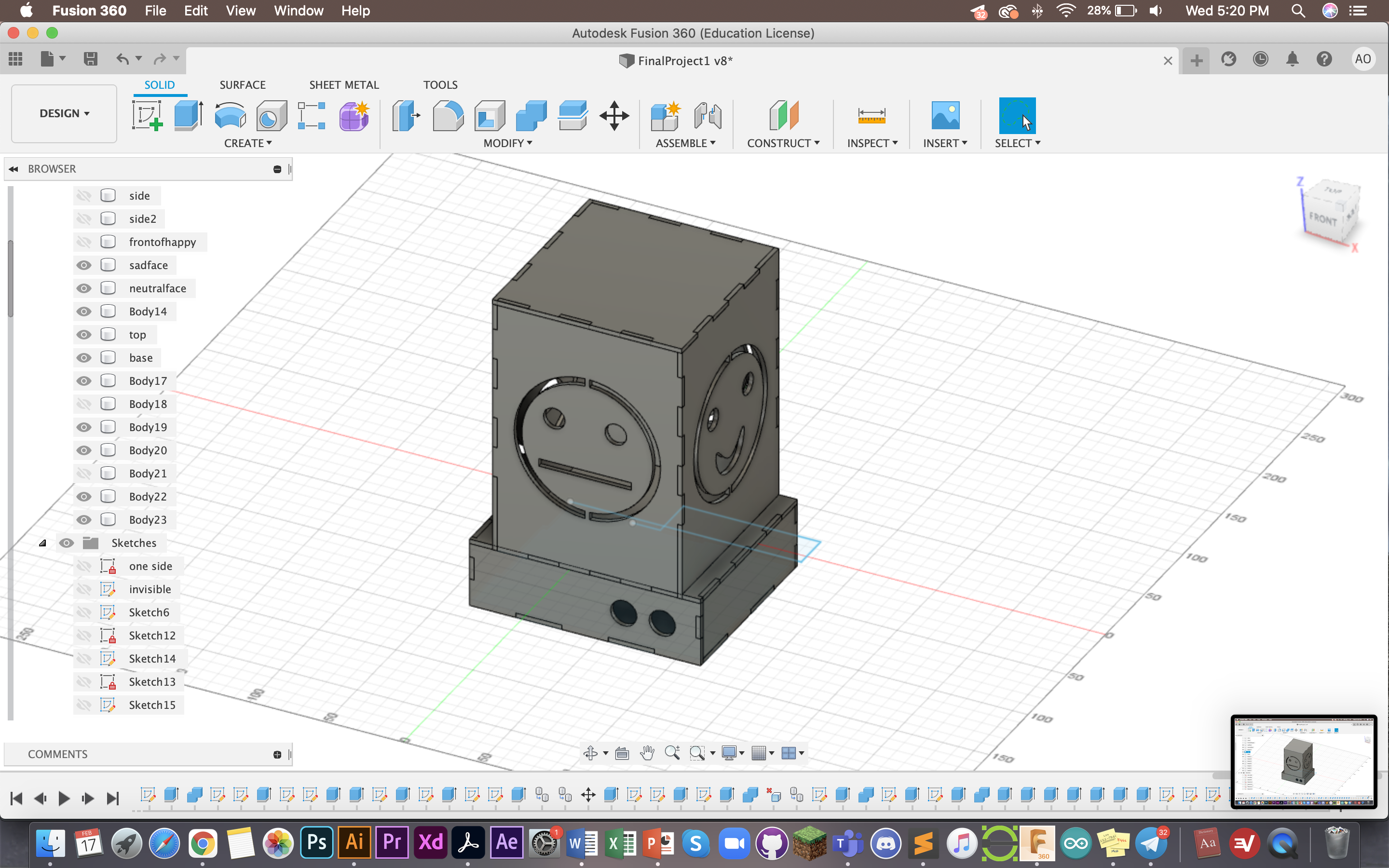
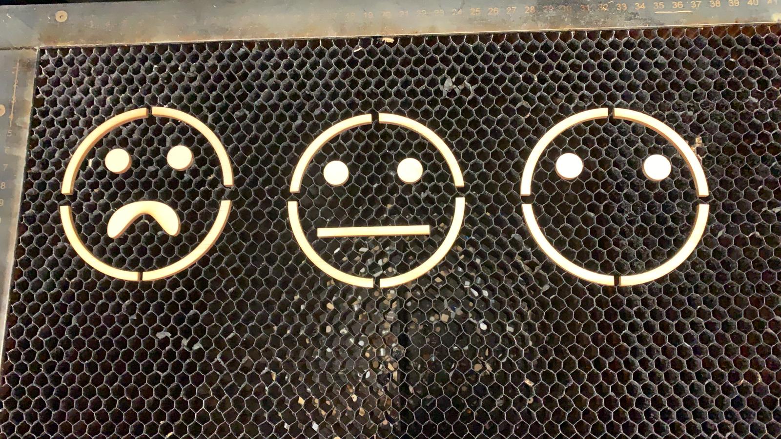
After removing the layers, I started designing the smiley face. I measured the centre of the box and cut out two circles with a connector inebetween to hold it together. To do this I measured the diameters and tried to match them accurately. I repeated this for all four sides of the box.
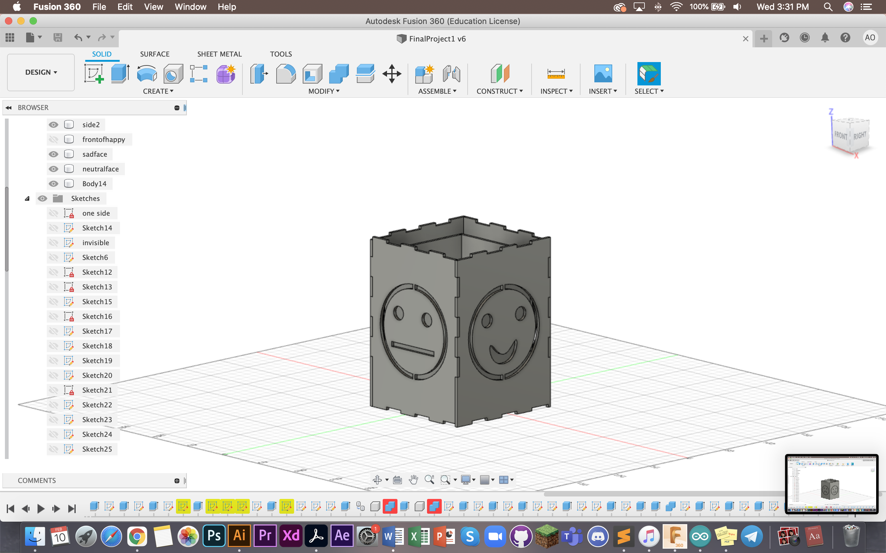
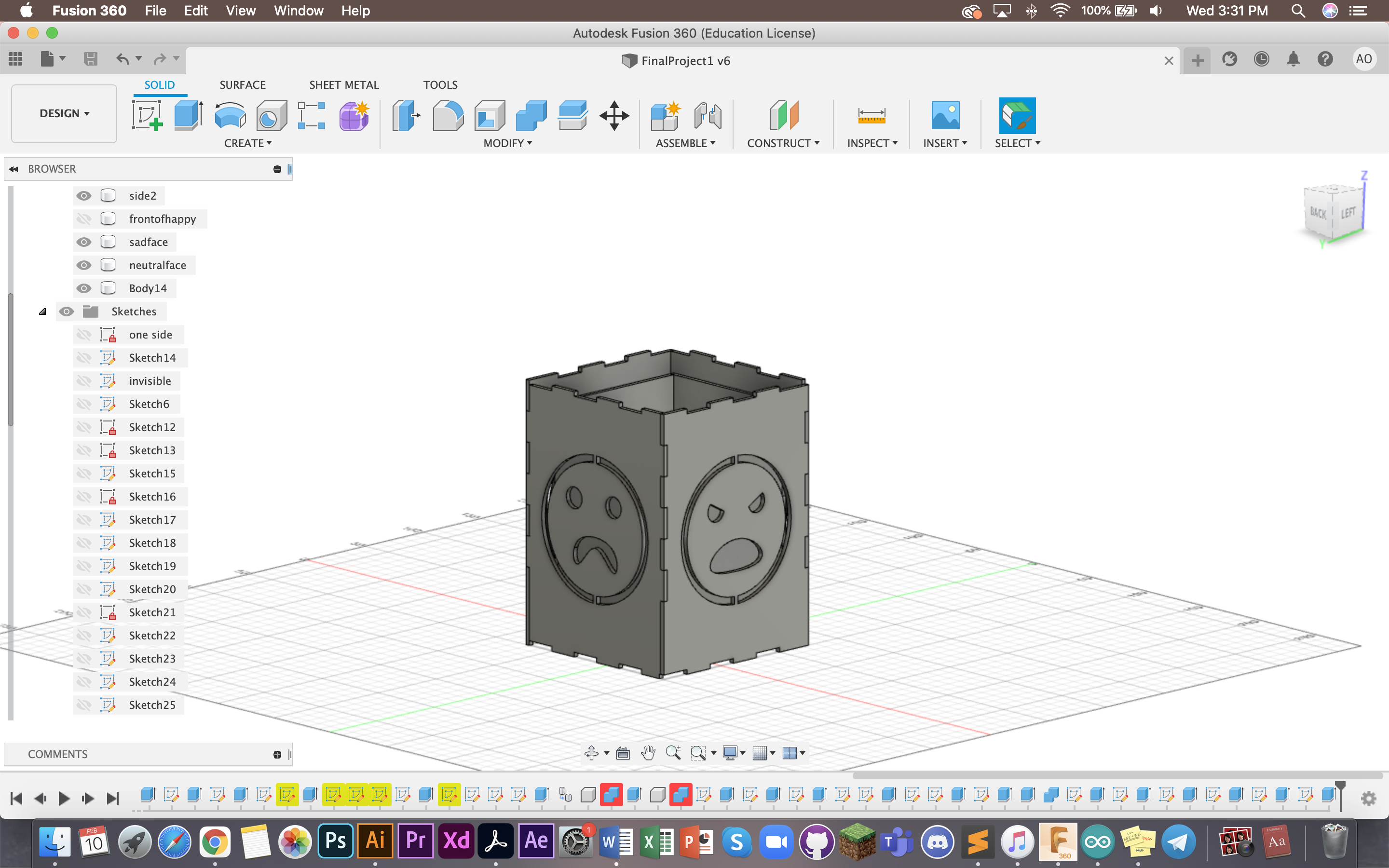
This is the end product of all four sides. This is following my concept of "literally" showing different moods on the four different sides of the lamp.
I also made use of the combine>cut (keep tools) tool (elaborated under Computer Controlled Cutting tab). As you can see here each side is nicely cut out with the "tooth" method.
Here is the box designed, placed below the lamp to hide and keep the UNO board. As you can see, I have also cut and measured holes for where the plug and HCSR04 will be sticking out of.
I also needed to design the 3D print part. What I planned for is to have a cylinder in the middle to coil my LED around so that the light will be all around the lamp.
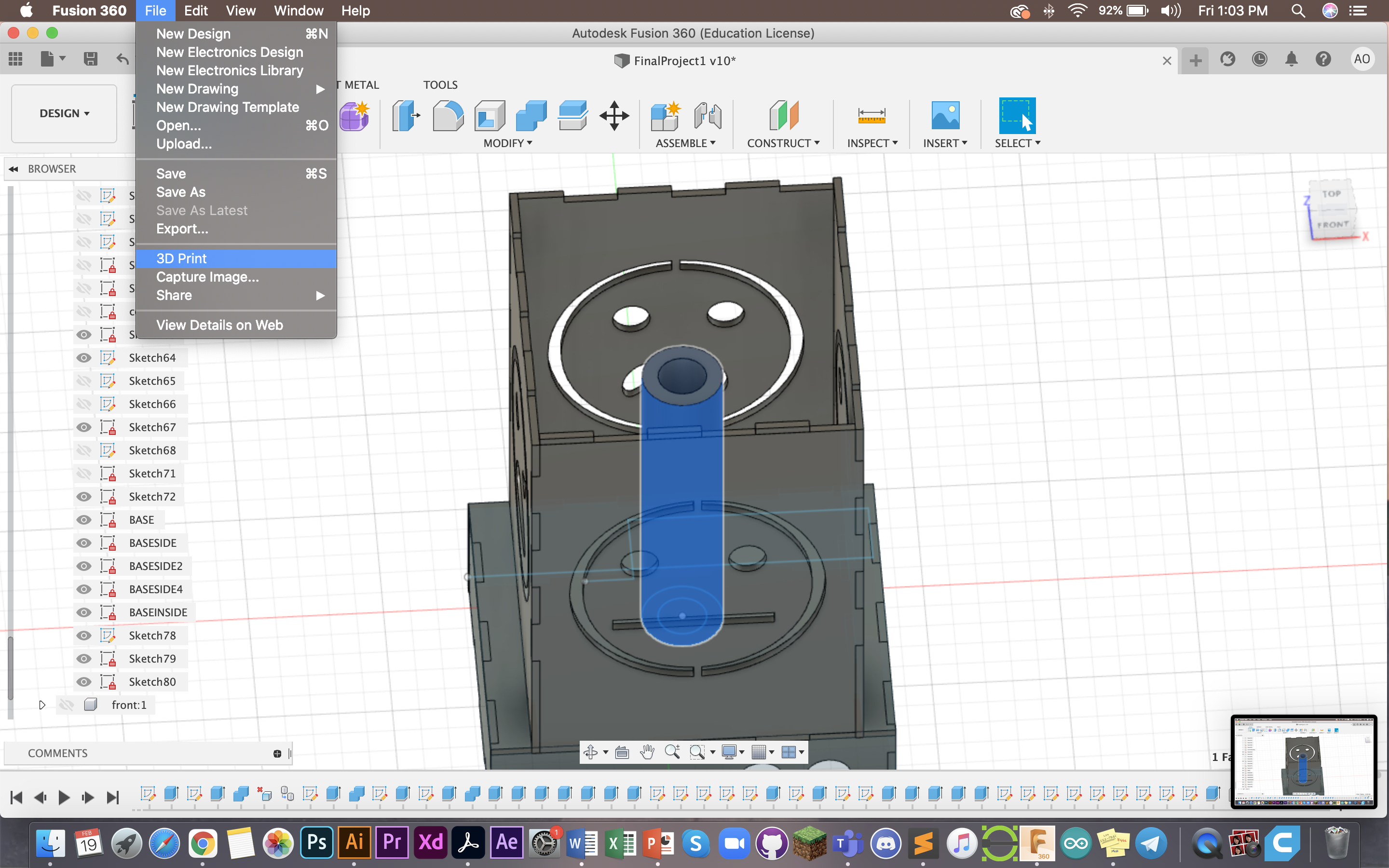
I made two circles in the middle and extruded it to 100mm.
This marked the end of my CAD, next was to laser cut the pieces and 3D print my cylinder.
3D Printing
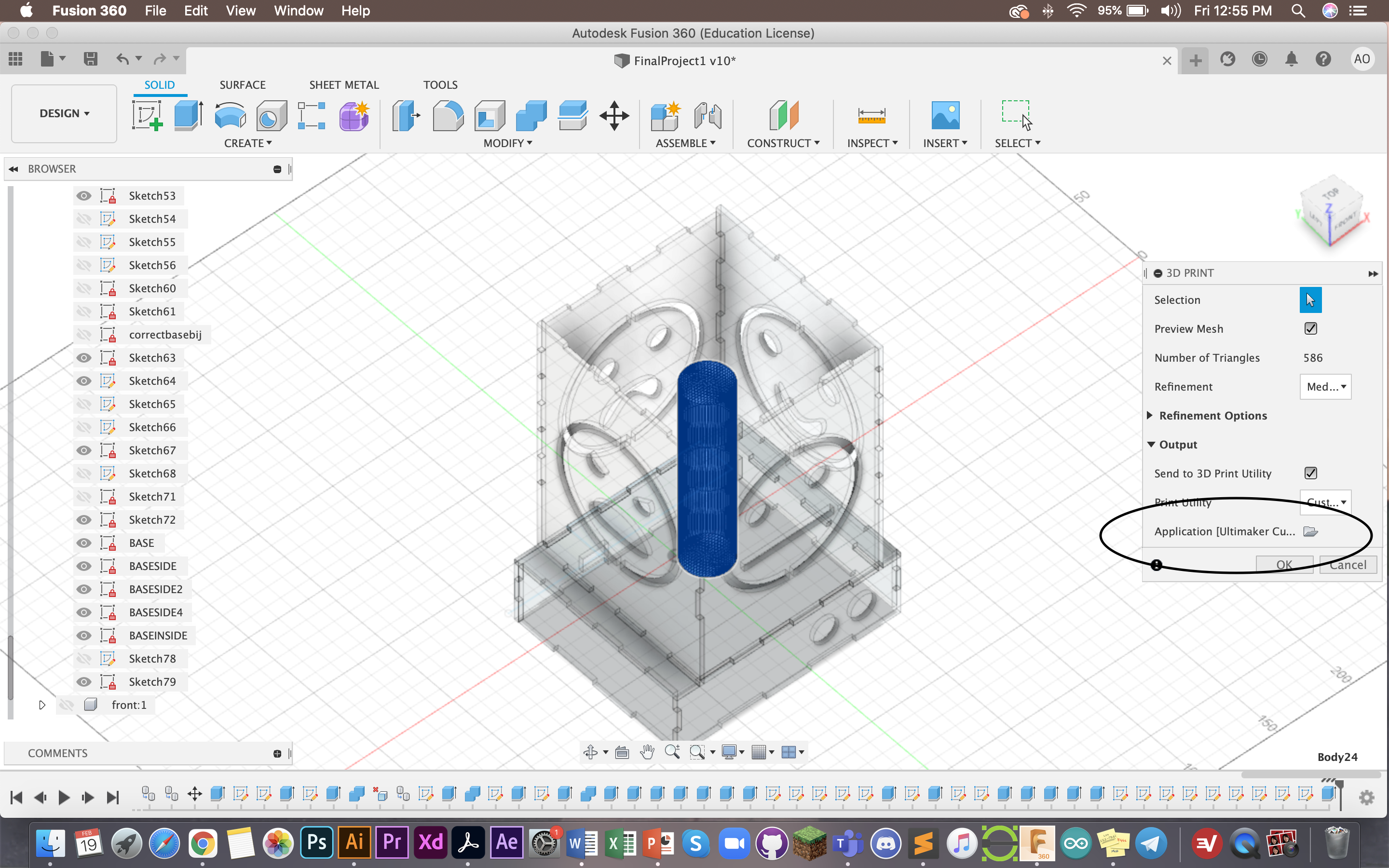
Here I was exporting to Ultimaker Cura. I did not manage to get a screenshot of my settings but I chose skirt, and 5% infil.
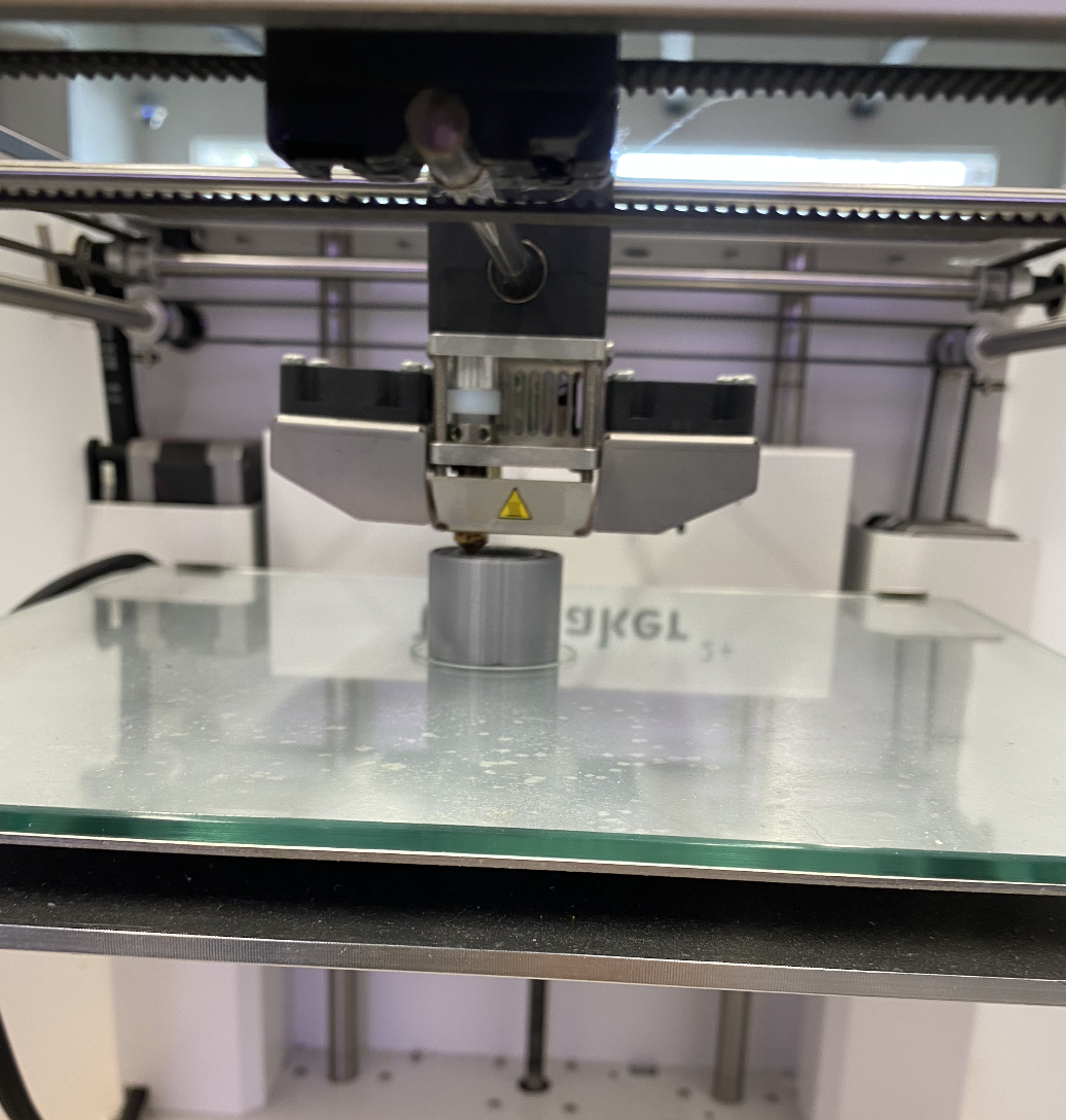
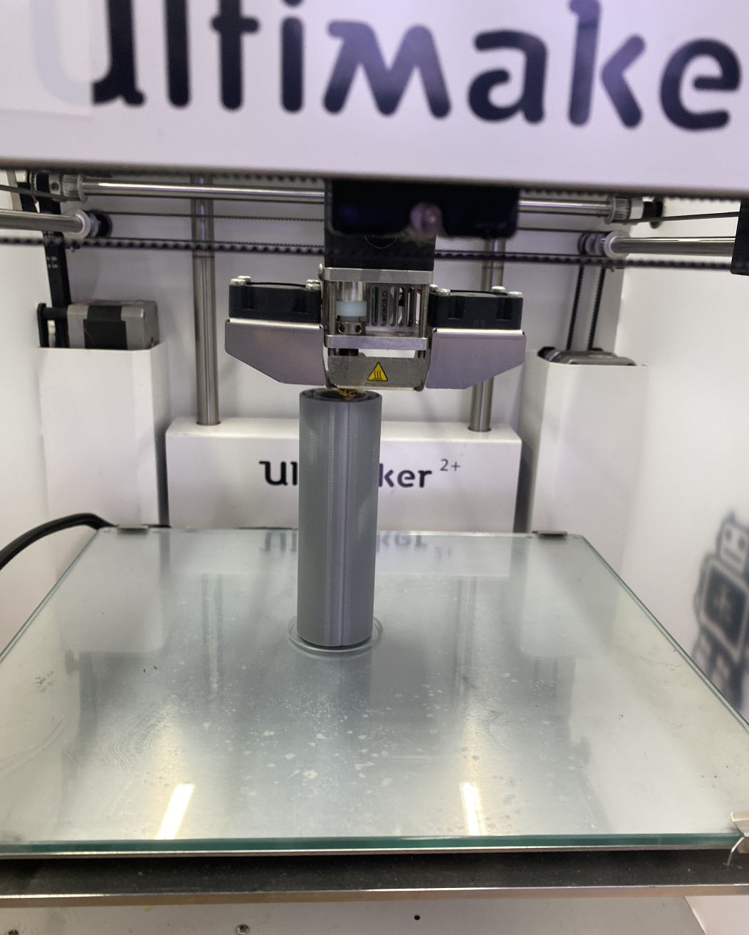
Here it is getting printed. Reminder that it is good/impt to stand and watch at least the first part of your print to make sure there are no errors or issues.
Laser Cutting
The only material we needed to laser cut was on the 3mm plywood, as I didn't use LibreCAD, I arranged the pieces on CorelDraw closely to print. Putting them closely also allows less wastage of material.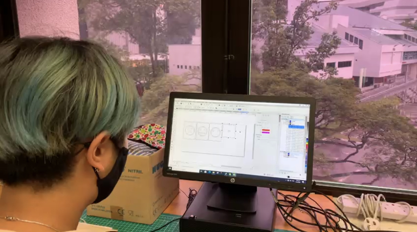
This is me arranging the parts.
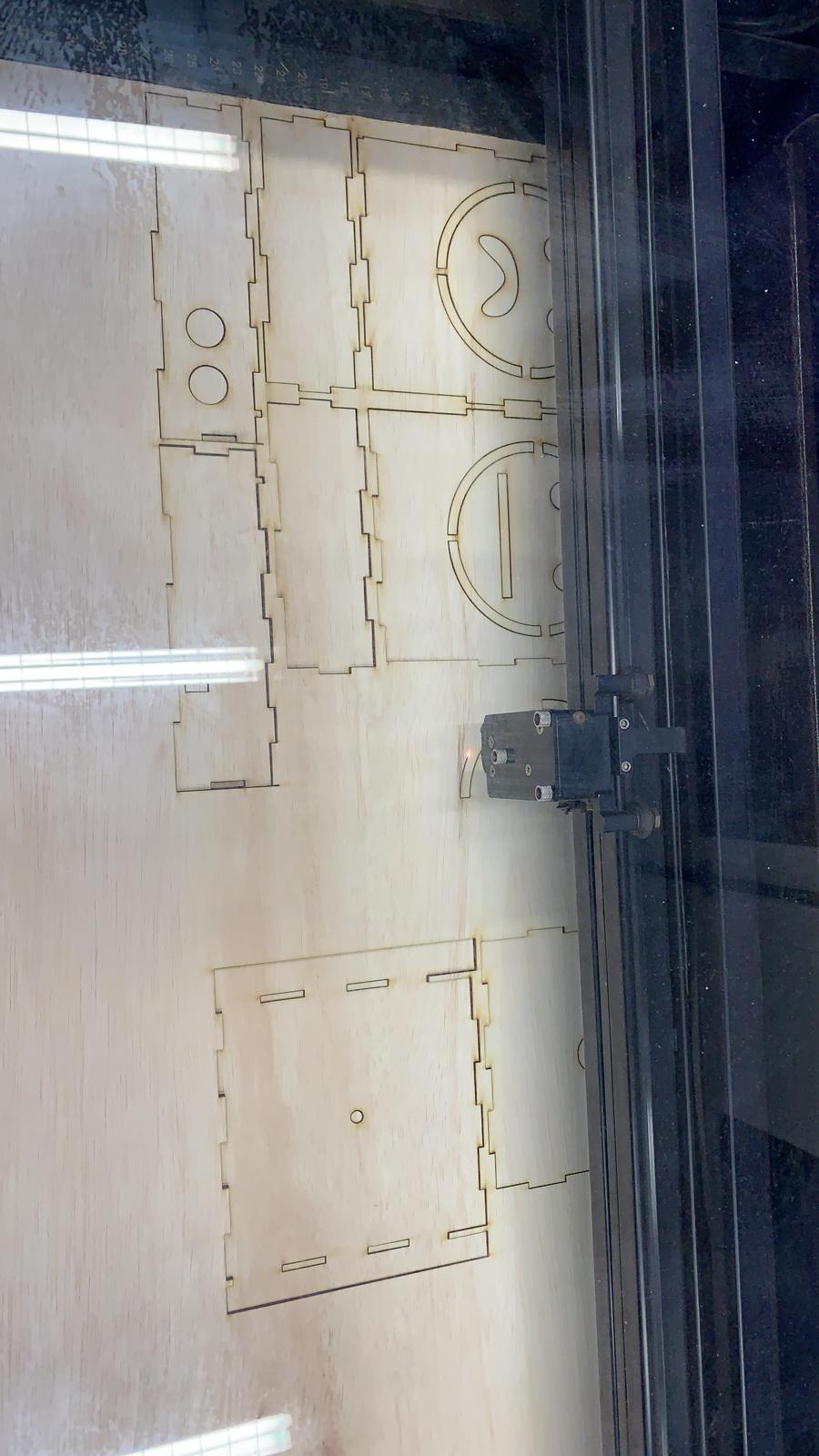
These were the pieces in the process of being laser cut. Since this was 3mm plywood, the settings were 40% power, 6% speed, 200 PMI and 3mm. \
These were some cute leftovers hehe :3
Electronics
First I tested out on TinkerCAD. My input was the HCS204 Ultrasonic Distance Sensor and my output was the LED NEOpixel strip.
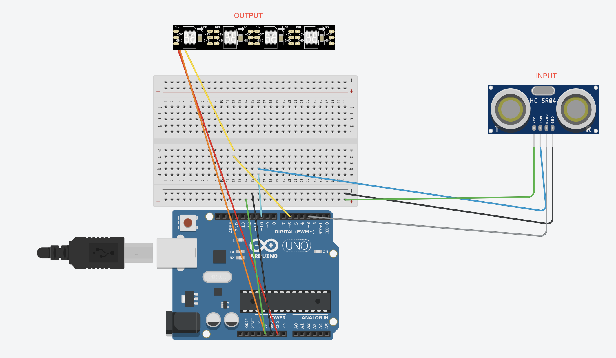
In my final I connected it as
LED:
GND = GND
5V = 5V
DIN = 9
HCS204:
TRIG = 5
ECHO = 6
GND = GND
VCC = 5V
One of the problems I faced was that the wires broke off, hence had to re-solder them.
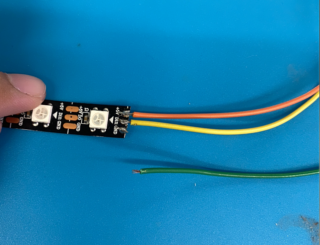
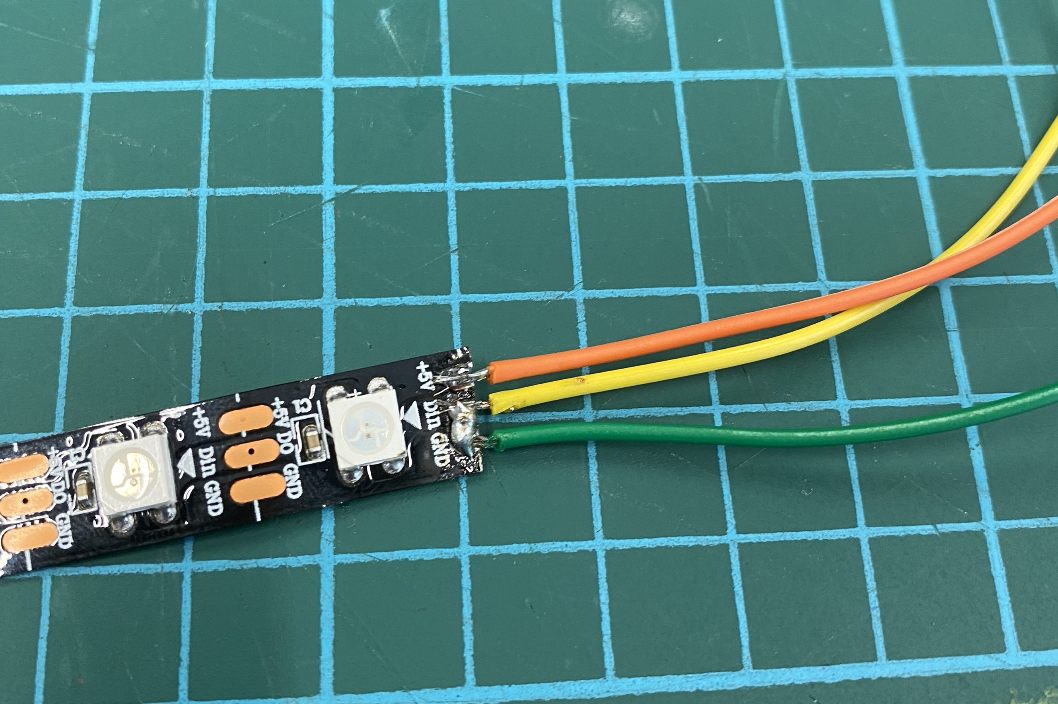
However I had soldiered such that DIN and GRND became connected, hence the LED still did not work. I tested the LED by running source code on the LED on it. I recieved some help to re-soldier it wel, after which the LED began to work again.
Programming
My source code was the ADAFruit Neopixel (strand test) and HCSR04 ultrasonic sensor. I downloaded both from the Aurdino sketch library.
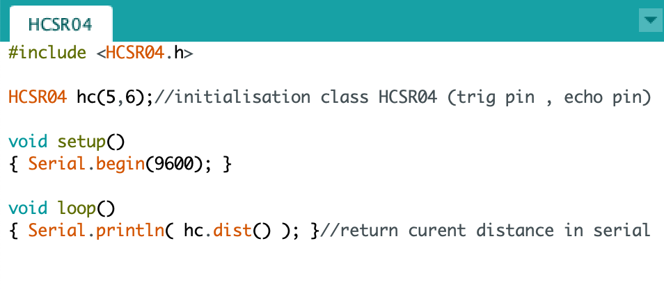
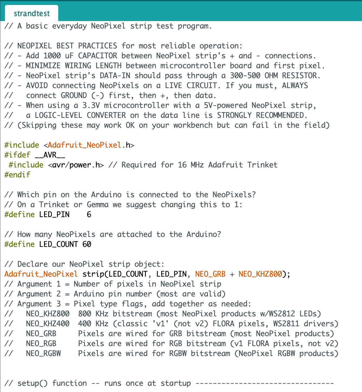
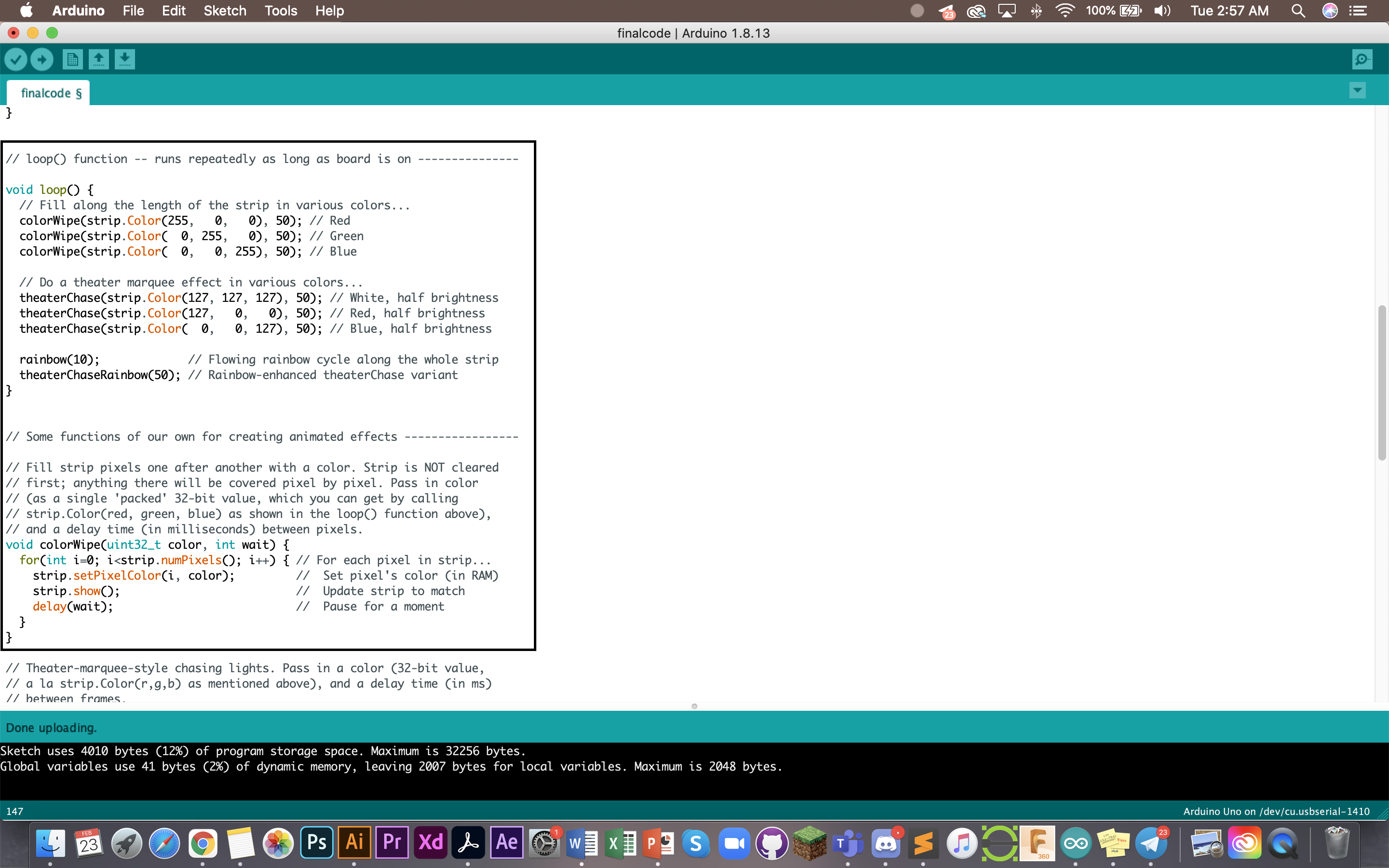
The codes above are screenshots of source codes from the Aurdino library. I picked and chose from there what code to combine and use for my project.
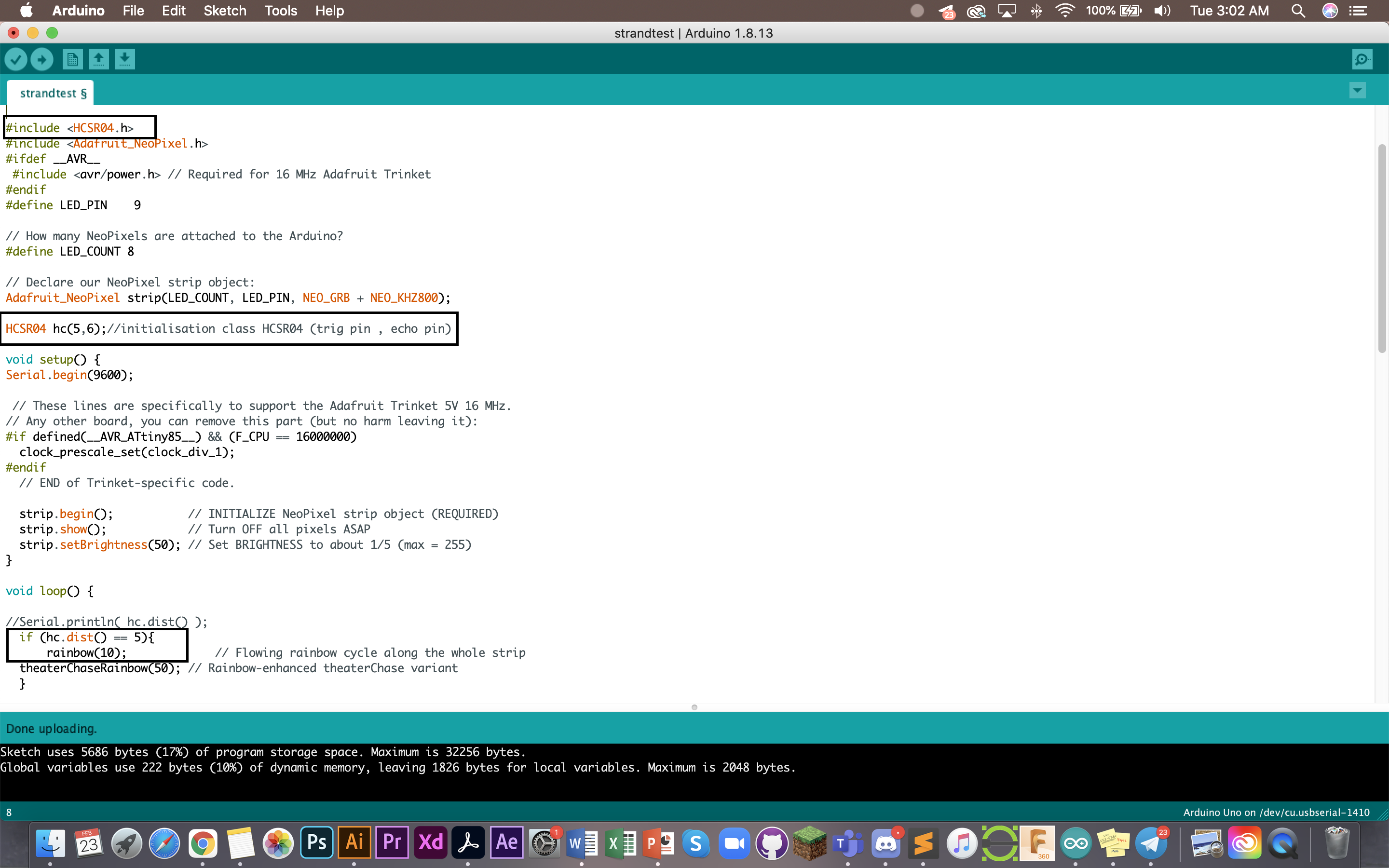
Below is the code that was combined and adapted for this project. I chose the rainbow colours as well as wanted it to remain 2 colours at the end.
Below is the inserted code for the HCS204. by #include it combines the two together, thus allowing me to use the HCS204 to affect the light.
hc (5,6) as you can see in the notes next to it allowed me to write the units that each pin was into.
The highlighted rectangle at the bottom is the code for the distance. The larger the unit, the further the distance between the surface and distance sensor before the light gets affected.
You can watch a short 30 second video of the code working on the UNO board here.
This is my full code:
#include
#ifdef __AVR__
#include
#endif
#define LED_PIN 9
#define LED_COUNT 8
Adafruit_NeoPixel strip(LED_COUNT, LED_PIN, NEO_GRB + NEO_KHZ800);
void setup() {
#if defined(__AVR_ATtiny85__) && (F_CPU == 16000000)
clock_prescale_set(clock_div_1);
#endif
strip.begin();
strip.show();
strip.setBrightness(50);
}
void loop() {
colorWipe(strip.Color(255, 0, 0), 50); // Red
colorWipe(strip.Color( 0, 255, 0), 50); // Green
colorWipe(strip.Color( 0, 0, 255), 50); // Blue
theaterChase(strip.Color(127, 127, 127), 50); // White, half brightness
theaterChase(strip.Color(127, 0, 0), 50); // Red, half brightness
theaterChase(strip.Color( 0, 0, 127), 50); // Blue, half brightness
rainbow(10);
theaterChaseRainbow(50);
}
void colorWipe(uint32_t color, int wait) {
for(int i=0; i
strip.show();
delay(wait);
}
}
void theaterChase(uint32_t color, int wait) {
for(int a=0; a<10; a++) {
for(int b=0; b<3; b++) {
strip.clear();
for(int c=b; c
}
strip.show();
delay(wait);
}
}
}
for(long firstPixelHue = 0; firstPixelHue < 5*65536; firstPixelHue += 256) {
for(int i=0; i
strip.setPixelColor(i, strip.gamma32(strip.ColorHSV(pixelHue)));
}
strip.show();
delay(wait);
}
}
void theaterChaseRainbow(int wait) {
int firstPixelHue = 0;
for(int a=0; a<30; a++) {
for(int b=0; b<3; b++) {
strip.clear();
for(int c=b; c
uint32_t color = strip.gamma32(strip.ColorHSV(hue)); // hue -> RGB
strip.setPixelColor(c, color); // Set pixel 'c' to value 'color'
}
strip.show();
delay(wait);
firstPixelHue += 65536 / 90;
}
}
}
Conclusion
A couple of issues encountered were 1. prototyping the box to be exact fits.
As I changed my design 3 times, there were bound to be some mishaps. One of my bases were not properly cut due to inaccurate dimensions. This also made designing and fixing difficult and confusing for me. So one thing I learned from this is to really check your materials prior to starting on the design as well as setting you dimensions exact to what you want to prevent time wasted needing to change the design over and over again.
My 2. issue and main issue was learning how to connect where to what. I was not very familar with VCC and the Ultrasonic Distance Sensor. So I did some more reading up to understand it better. This helped a lot later on and provided clarity for me to understand how things flowed such as input and output.
Improvements that can be made:
I think it would be nice if the electronics can be hidden within just one box. Right now I need two boxes which makes the lamp very bulky. However, I think with a more concise design, the UNO box can fit inside the lamp the same place the LED is in. The LED was also not as bendable as I expected. An improvement that can be made is to find a better more efficient way to light up the whole box other than roping it around a tube like what I did.
Hero Shots
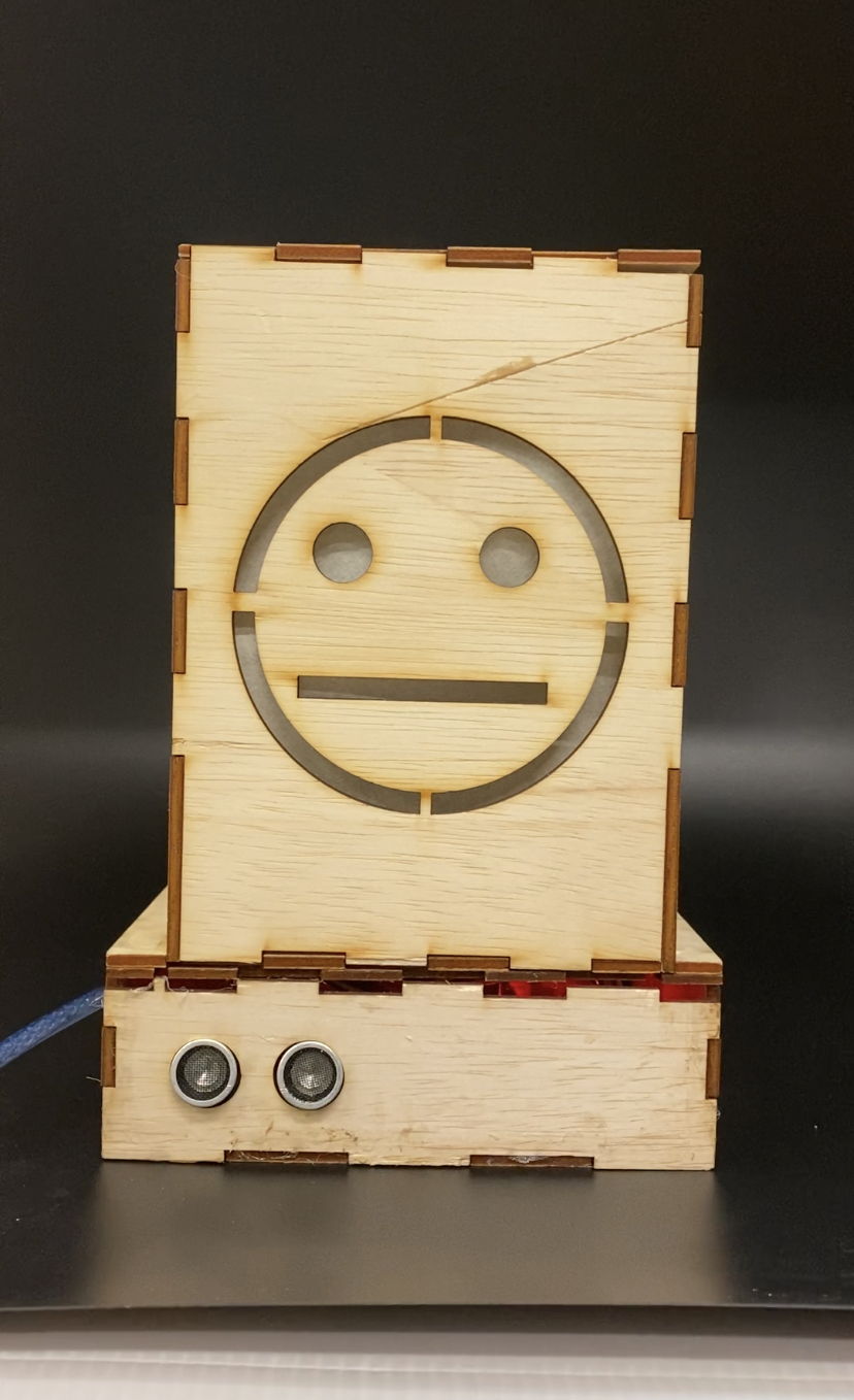
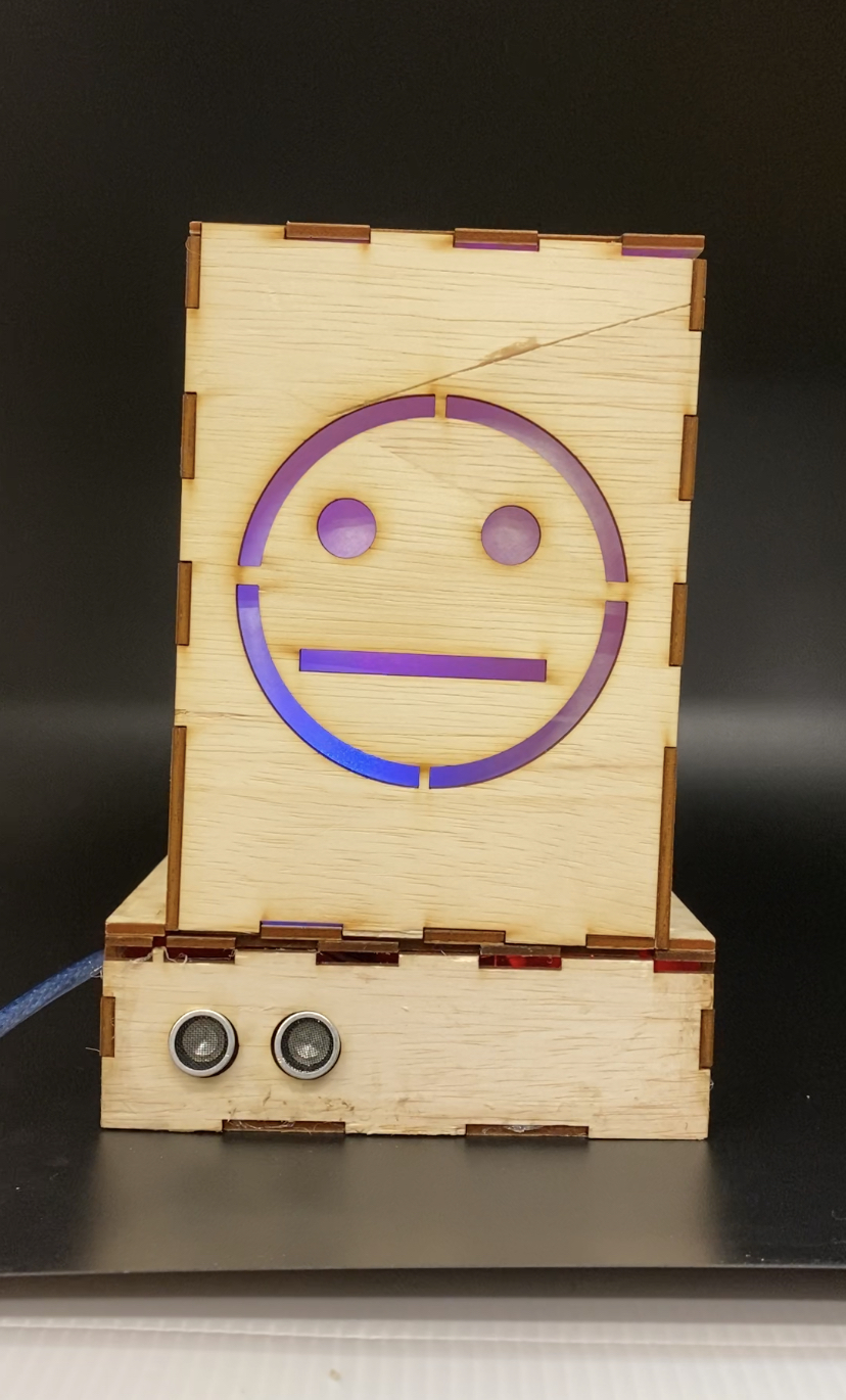
Thank you! That's all :)
Last updated: 23rd Feburary 2021